28V Gate Drive Module Calibration
Test Points used in calibration:
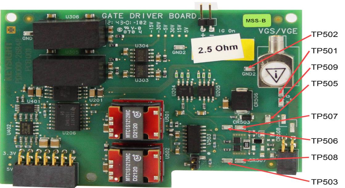
Test Point Connections on Low-Side Gate Drive Module
Test Point Description IG On Used to measure Gate Current On. Connector for N2819A Differential Oscilloscope Probe TP501 Connector for Calibration test hook (Gate Voltage Source Calibration, Gate Resistance Calibration) TP502 Connector for Calibration test hook (Gate Voltage Source Calibration) TP503 Connector for Calibration test hook (Gate Resistance Calibration) TP504 Connector for Calibration test hook (does not exist, not used for calibration) TP505 Connector for Calibration test hook (Gate Current Calibration) TP506 Connector for Calibration test hook (Gate Resistance Calibration) TP507 Connector for Calibration test hook (Gate Current Calibration, Gate Resistance Calibration) TP508 Connector for Calibration test hook (Gate Resistance Calibration) TP509 Connector for Calibration test hook (Gate Resistance Calibration)
The output variant of the ±28 V Gate Driver Boards requires different calibration steps.
The Split-Variation has separate RG,ON- and RG,OFF-paths while the Common-Path variation uses only the RG,ONpath.
Calibration Requirements
Calibration requires the B2902A Precision Source/Measure Unit (SMU) and the following cables/adapters:
- 1251-2277 Banana to BNC Adapter, quantity 1.
- 8121-2816 BNC to SMA Cable, 1 m, 50 W, quantity 1.
- 1168B Standard Probe Kit, quantity 2.
IMPORTANT: Make certain the B2902A is set for the correct ac line frequency. See Set/ Verify AC Line Frequency and Date/Time on the B2902A
Calibration Procedure
To begin the Calibration & Compensation process:
-
Turn on the PD1500A Test System and allow it to warm-up for at least one hour.
- Install both the High-Side and the Low-Side 28 v Gate Drive modules on the PD1500A Test Fixture. The system reads the EEPROMs on the Gate Drive Modules and automatically selects the appropriate Calibration procedure.
- Remove the oscilloscope probes from the DPT test fixture and test modules. Do not remove them from the oscilloscope. Probe are re-installed on the gate drive module as required for the calibration.
- Select Calibration & Compensation from the Settings drop-down menu.
- Follow all on-screen instructions.
Go to: